


*This is an inside look at The May 2015 Acoustic Guitar Workshop at Eric Schaefer Guitars. The class is an 8 day intensive course in Guitar Making with a maximum of only 2 students to a class. For more information on the courses go to Guitar Making Classes.
In May of 2015 Chris (left) and Jim(right) built their own OM size acoustic steel string guitars with no prior experience, in just 8 days. The following is a walk-through of the steps they took.
Day 1…
Jim and Chris lay out the bracing pattern and mark the X-braces in preparation for notching. The X-braces must each be notched at their point of intersection to accept both braces and still allow for proper mating with the soundboard surface.

Once the area is marked out for notching, the notch is cut by cutting kerfs about 1/16″ apart, removing the kerfed material with a chisel and finally cleaning up the notch with a file.

The intended radius for the top is transcribed onto the side of the X-braces. The idea is to put a radius into the mating surface of the braces. That way the top will be forced to conform to the radius. A block plane removes the bulk of the material on the braces and then the fine-tuning happens on a radiused dish covered in sandpaper. The same radius is applied to the tone bars.

The X-braces are glued first. The radius dish is used as a bearing surface for the glue job.

While the glue sets for the X-braces Jim begins preparing the neck block and end block for assembly to the sides. The sides are placed in a mold with interior mold clamps. Jim is marking the centers on both blocks in order to properly align them.

The neck and end blocks are glued to the sides in alignment with the form’s centerline. A carefully planned assemblage of cauls, C-clamps and cam camps are used to ensure good distribution of pressure. Since the lower bout of this mold has a continuous curve, the mating surface of the end block was radiused to fit the mold prior to glue up.
On the left, the neck is prepared for routing of the truss rod channel.

Chris has shaped the bridge plate and is gluing it in place using a caul to allow clearance for the clamps over the x-braces. Notice how the clamps are all pulling in the direction of the x-brace. This is so the x-brace can act as a fence to keep the bridge plate from “swimming” off its mark.

Jim begins carving the taper into the x-brace ends. Ultimately, the x-brace ends will be tucked into the kerfing of the sides for continuity of structural support across the top and for transmission of tone out to the rims of the instrument.

Chris prepares the tone bars and the finger braces. The ends of the braces have been angled to butt up seamlessly against the x-brace arms and he is marking the areas where the taper will begin. Unlike the x-braces, the tone bars and the finger braces will taper in both directions leaving a plateau in the middle.

The end of the brace that tapers in toward the x-brace is easier to carve before it is glued in place, so Jim and Chris stick the braces to a piece of scrap wood with double stick tape and carve the inside taper.

The braces are then glued in place.

The upper transverse bar and the fretboard graft are also glued in place at this time. Later the upper transverse bar will also be carved to a taper so that the brace ends tuck into the kerfing.

In the meantime, Jim moves on to the back plate. He aligns the backstrip with the jointed centerline of the back. Using a straightedge as a fence, he glues the backstrip in place, again mitigating the “swimming” problem by allowing the cam clamps to pull in the direction of the fence.

Of course, you can never use too many clamps!

Jim gets to work carving the rest of the soundboard braces.

Unlike the x-braces, the tone bars and finger braces will not tuck into the kerfing on the sides. Rather, these braces will be “feathered” into the soundboard. This means that the ends of the braces will be carved down to nothing. If executed well, the feathered braces will appear to simply flow into the plane of the soundboard.

Jim takes a break from carving braces to round over and smooth the backstrip using a block plane and sandpaper.

Meanwhile, Chris is gluing the soundhole braces after shaping them to fit. The soundhole braces connect the x-braces to the upper transverse bar. They also reinforce the area around the soundhole.

The back braces can be glued all at once using cauls to distribute pressure.

Chris drills a hole in the center of the upper transverse bar so that the truss rod can be accessed later with an allen wrench through the soundhole.

Using a round file, the hole is further slotted in the direction of the soundboard. At the same time, the fretboard graft is being relieved by the file so as not to impede truss rod adjustments later on. The blue tape under the file is there to remind Chris to stop before accidentally filing into the soundboard.
Chris also glued a thin shaving of spruce at the x-brace intersection to hide the seam there. The blue tape is “clamping” the spruce shaving in place while the glue sets.

Chris and Jim taking a break to show off their work and get some fresh air!

The top and back bracing are further refined by scraping with scrapers and smoothing with sandpaper to 220 grit


Ah, decisions… decisions! Jim and Chris pick through a pile of exotic, figured and unfigured woods to determine the best fit for the strictly aesthetic appointments on their guitars: headplate, heelcap, and endwedge.

While there are no hard and fast rules for artistic discernment, it is a safe bet to choose something that contrasts with the neck, back and sides. Keep in mind that certain woods, particular those with a bright reddish color, will darken or dull in time.

Jim and Chris begin work on the endwedge. The purpose of the endwedge is to cover up the seam where the sides meet on the endblock. First the endwedge is cut to shape and aligned with the center of the endblock. The outline of the endwedge is traced onto the sides. Note: The seam where the sides meet is not a reliable measure of the guitars true center.
Jim and Chris use a 10″ dovetail saw to cut down to the endblock on the two tapered lines. Cam clamps hold a small block with a straight edge on the outline as a guide for the saw.


Chris makes multiple kerfs with the dovetail saw to the inside of his first two kerfs. Then he pops out small chunks of wood by wedging a chisel along the grain lines which are perpendicular to the kerf cuts.

Jim follows up his chisel work with a dremel tool to clean up what was missed by the chisel. A sturdy base and a fine downcut bit help ensure a smooth, clean pocket.

Jim glues his endwedge in the pocket simply by applying titebond to the endwedge, lightly clamping with 2 spring clamps and then tapping the wedge lightly into place with a hammer and a hard block. After leveling with a random orbit sander, his endwedge looks like this:

Chris has installed his endwedge and leveled it flush with the sides. He is lightly brushing ebony dust into any gaps between the endwedge and the sides. Dropping a bead of water-thin superglue along the ebony-dust-fills and cleaning up with sandpaper will hide the gaps.
In the background, Jim has begun work on the fretboard. He is trueing up the edge of a rosewood board on a shooting board with a #5 jack plane.

Chris begins work on his fretboard by first thicknessing it on the drum sander.

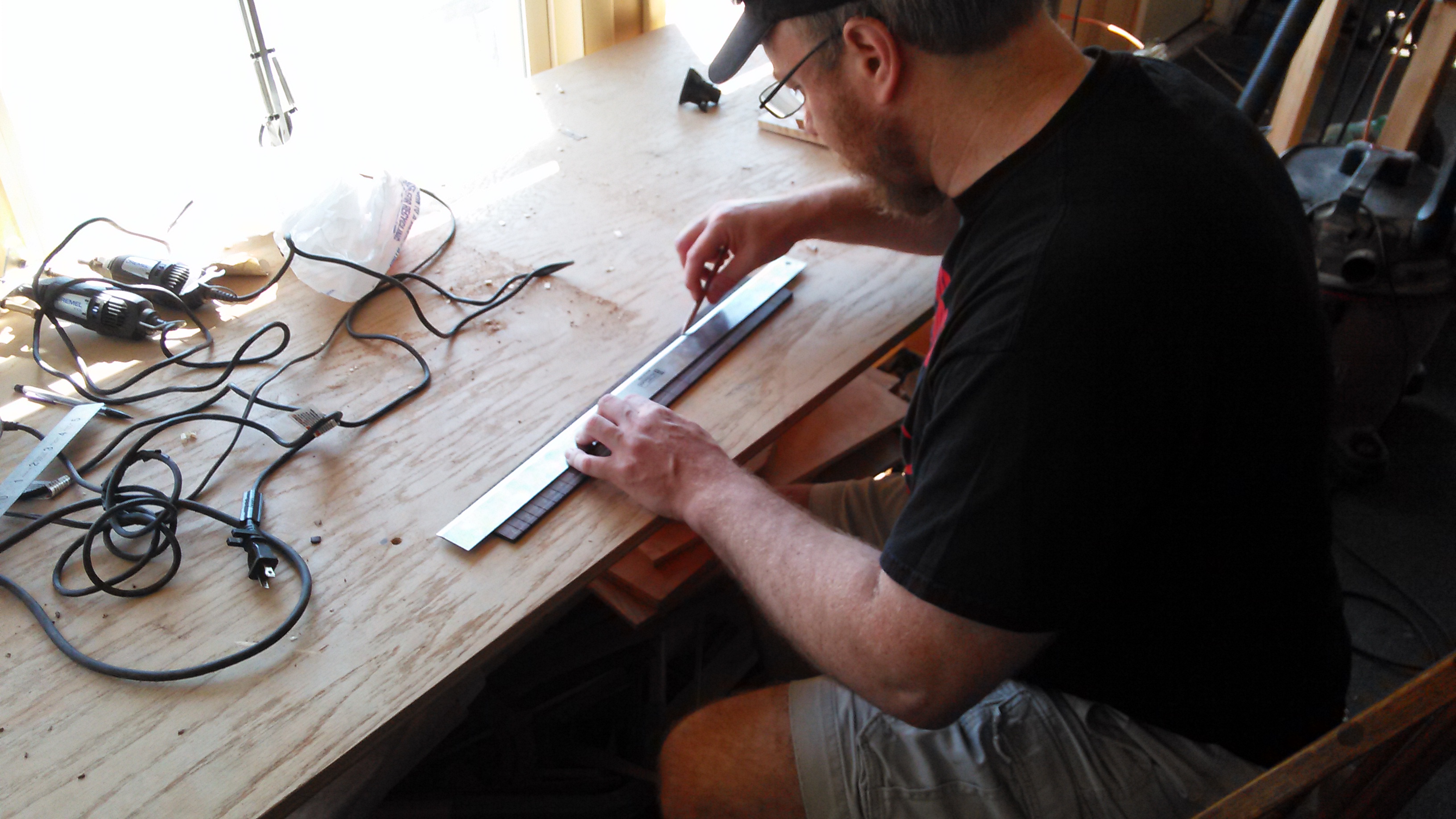
After trueing up one edge of the board, Chris begins slotting the fretboard. The board is fastened with double stick tape to a metal fret slot template for a 25.34″ scale length. A specialty table saw blade with a 0.023″ kerf is used to match the frets tang. The fence has an index pin which accepts the index notches of the fret slot template. The depth of cut is set to be greater than the depth of the fret tang by a small amount to take into account future levelling of the fretboard prior to installing the frets.

Jim has slotted his fretboard and is now tracing the taper of the fretboard. Steel string fretboards are narrower at the nut and wider towards the soundhole end. Jim sets the taper by first finding center at the nut and center at the 14th fret (or the location where the neck meets the body). He then marks out the width at the nut and the width at the 14th fret and connects his marks with a straightedge.
Chris and Jim cut just outside the line and then plane down to the taper on a shooting board with a jack plane.
 Chris double stick tapes his fretboard to the workbench and begins sanding with a radiused block and 80 grit sandpaper. The block is radiused to 14″. It is important to be mindful of any tipping or tilting of the block while sanding. Covering the fretboard surface in chalk first will reveal any discrepancies in your sanding form, and help you determine where your high and low spots are.

Jim, on the other hand, puts away the fretboard for now and resumes work on the sides. The sides are proud of the neck block and end block and they need to be brought down level with the blocks. First, Jim removes just enough side material to be able to rest a straightedge across both blocks. This can be done quickly with a chisel as long as you only chisel in the area above the blocks and you chisel in TOWARDS the side seam. This is VERY important! If you use the chisel in the other direction you will catch the grain and split the sides far down its length, likely ruining your entire side.

Now with the straightedge resting across both blocks as a visual aid, Jim begins to plane the rest of the side material. A block plane or a spokeshave makes quick work of it. The goal is to bring the sides down flush with the blocks without reducing them lower than the blocks. For this reason, Jim stops short of flush so that the final 1/32″ or so can be achieved on the sanding dish. It is important to note that the end block is taller than the neck block so more material is being removed from the neck block end of the guitar. This sets the front to back contour of the sides.

Chris begins fretting his fretboard. First the fretwire is degreased with naphtha and bent to a radius greater than the radius of the fretboard (greater than 14″). This is to facilitate seating of the frets on the ends. Each fret is cut to be slightly oversized for its slot. The excess will be nipped off later. A brass headed dead-blow hammer is used to prevent recoil. A hard granite block is placed under the fretboard, also to prevent recoil.
For each fret, first the ends are tapped in, each with a single, sharp blow from the hammer. Then a series of sharp blows, starting from the middle and working out towards the end, seats the rest of the fret. Keeping a loose grip on the hammer, much like a drummer’s grip on drum sticks, is good technique.

Meanwhile, Jim has brought the sides down flush with the blocks by sanding the last little bit on the radius dish. He is using a 40′ radius for the top and a 15′ radius for the back. He is now gluing the kerfing to the sides. It is easier to glue small strips of kerfing than it is to glue one long, continuous piece. The kerfing is clamped in place with clothespins. Each clothespin is wrapped with a rubber band for added clamping force. The kerfing is glued just a hair proud of the sides so that it can be radiused later on the radius dish.


Chris has fretted the entire board and now he is clamping a specialty caul to help seat any fret ends that may be poorly seated. The specialty caul is nothing more than a reject factory fretboard with brass rods epoxied to the edges. The brass is soft and doesn’t mar the frets when clamped.

With the caul clamped so that the brass rods seat the fret ends, Chris runs a bead of water-thin CA glue down the tang of each fret.

Chris now begins to catch up with Jim on the sides. In the picture below he is using the radius dish to prepare the sides for kerfing. The mold clamps hold the sides in place and keep them from splitting due to the sanding action.

Jim is checking the depth of his fret slots. It is critical that the slots are deeper than the fret tang. Otherwise the frets won’t seat properly.

To deepen the slots, he uses a special dovetail saw with a very precise 0.023″ kerf because it is also critical that you do not widen the slot in the process of deepening it.

Chris has turned his attention to the back plate. The brace ends are tapered to tuck into the kerfing just as the x-braces and upper transverse bar were. Now Chris is trimming the brace ends so that they tuck into the kerfing but not through the sides. He uses a small razor saw and a chisel.

Similarly, Jim has marked where the neck and end blocks overlap the backstrip and he is trimming the backstrip to fit. He also uses a razor saw and a chisel. The razor saw kerfs the material and the wedging action of the chisel pops out the material between the kerfs.

Jim and Chris have filed the fret ends flush with the fretboard using a flat single-cut file on a shooting board. They have also beveled the fret ends with the file and they are now using a specialty needle file to smooth over and take the sharp bite out of the fret ends so they will feel good on their playing hand.


Now they place the sides back in the mold. They have marked where the back braces meet the kerfing and notched out those areas using a dremel tool with a base. They are now radius sanding the kerfing to match the intended radius of the top and the back plates: Jim is using a 40′ radius for the top and a 15′ radius for the back, while Chris is using a 28′ radius for the top and a 20′ radius for the back.

With the kerfing notched and radiused, the back is now ready to be glued to the sides. The sides are kept in the mold in order to keep its shape. The radius dish for the soundboard side is used as a bearing surface.
To start, the radius dish is elevated with 3 scrap blocks underneath. This way clamps can easily and quickly slide into place. Special care is taken to apply the clamp force of each clamp down only on the kerfing and the blocks, and not inward where you can easily crack the plate.
It is best to leave this clamped overnight.

The next morning Jim and Chris prepare to close the box. The jointed centerline of the soundboard and the center of the neck and end blocks are carefully aligned and lightly clamped in place. Jim and Chris mark where the x-braces and upper transverse bar meet the kerfing.

Chris and Jim are trimming the excess off the upper transverse bar and the x-braces.

Chris notches out the kerfing to fit the x-brace arms and the upper transverse bar.

The soundboard is aligned, glued and clamped in much the same way as the back plate.

Of coures, a class would not be complete without an emergency trip to Lowe’s to replace a router bit gone M.I.A.

After lunch and Lowes, Jim marks out the spacing for his nut, the scale length and the neck tenon.

Chris uses a laminate trim router with a guide bearing to trim the excess overhang of the top and back plates. The guide bearing runs along the sides and ensures a flush cut. It is important to be aware of the direction you are running the bit. The bit should always be cutting down across the grain rather than up against the grain. If the bit runs up against the grain, the cutter can snag a grain line and tear out a large chunk. This is especially prominent in the waist area of the guitar. The solution is simply to run the router in the opposite direction so that the router is always moving “downhill.”

The top and back plates are now flush with the sides. Chris checks the area of the neck block where the heel of the neck will bear for square. He uses a hard, flat block and 80 grit sandpaper to make this area square to the soundboard surface.

Meanwhile, Jim has glued an oversized 1/8″ thick piece of Imbuia to his neckblank. This will be the headplate. A large, padded caul and many clamps are needed to evenly distribute the pressure. Drilling holes for locating pins (finishing nails with the heads trimmed off) help to keep the plate from swimming off its mark. Jim drills the holes for the locating pins in the areas of the headstock that will be removed later.

The soundboxes are complete!


Chris has stuck a wood template for the headstock shape to his neckblank using lots of doublestick tape. He is again using the laminate trim router and a guide bearing to rout out the shape. The guide bearing runs along the edge of the template. Before touching the neckblank with the router, however, Chris cleared as much wood as he could freehand on the bandsaw. The router bit simply cleared out the last remaining 1/32″ or so. You don’t want the bit to have to bite off more than it can chew.

Chris removes the template carefully by heating a metal spatula with a heatgun and separating the template from the neckblank. He then places the template on the show-face of the headstock and marks out the tuner holes by pressing a center-punch through the template holes.
The holes are then drilled on a drill press at a high RPM with a forstner bit and a scrap block underneath to prevent tear-out.

Chris and Jim align the center of the fretboard’s width at the nut with the center of the headstock. They also align the center of the fretboard’s width at the 14th fret with the center of the heel. Spring clamps hold the fretboard in place while they trace the outline of the fretboard onto the neckblank.
The excess material of the neckblank is then removed on the bandsaw to within 1/8″ of the outline.

At this point it is really starting to look like a guitar! There is still a lot of work to do, but Jim and Chris have earned a moment to admire their work and reflect upon what they’ve done. Keep in mind that the fretboard, neck, bridge, and body at this point are not glued in place. The heavy work of neck carving is about to begin!

Chris saws the excess fretboard length off at the 23rd fret slot.

Chris and Jim begin preparing both their neckblanks and guitar bodies for the mortise and tenon jig. The neck block area of the body must be square to the soundboard surface. The body is then placed in the mortise jig. The mortise is cut using a template and a plunge router with a guide bearing. The tenon jig is then set to cut the tenon at an angle that allows for optimal action adjustments later on. The tenon is also cut with a template and a plunge router with a guide bearing.

After the mortise and tenon are cut, Chris checks the fretboard again for alignment. 2 small holes are drilled at the 12th fret space precisely where the fret position markers will be. 2 locating pins help align the fretboard during glue-up. Chris glues the fretboard to the neckblank at this time, but not yet to the soundboard. The truss rod is placed in the truss rod channel with a dab of epoxy prior to gluing the fretboard down. The threaded adjustment end of the truss rod should be protruding from the tenon.

Jim has also glued the fretboard to the neckblank. He has now marked out the curve of the heel and is making relief cuts on the bandsaw before cutting along the curved line.

Chris marks out the width and length of the truss rod protrusion onto the soundboard. He uses a dremel tool to open the area for the truss rod protrusion.

Neck carving begins! The carving process is easy when you approach it by shifting focus between 3 distinct “sections” of the neck: The heel, the shaft, and the headstock. Once these areas are roughed out, it is simply a matter of blending the transition areas between headstock and shaft, and between shaft and heel. The headstock shape is already roughed out at this point, so that leaves the heel and the shaft as the primary focal points.
Chris and Jim begin by using a rasp to dig a “trough” at 2 points along the shaft: one near the heel and one near the nut end. The neck will taper in thickness from the nut to the heel, so they dig a slightly deeper “trough” at the nut end. A difference of 2 millimeters is pretty standard. They monitor their progress with a digital caliper.


Jim shifts his focus to the heel. He is chiseling the surrounding wood flush with the heel cap. After which he will bring the heel flush with the fretboard. The objective then is to remove the material between the fretboard and heelcap until a straightedge sits flat on the heel. The fretboard and the heelcap can be considered the hard points around which the rest of the neck is formed. It is therefore important not to inadvertently change the shape of the fretboard or heelcap at this point.


Chris also begins to shape the heel.


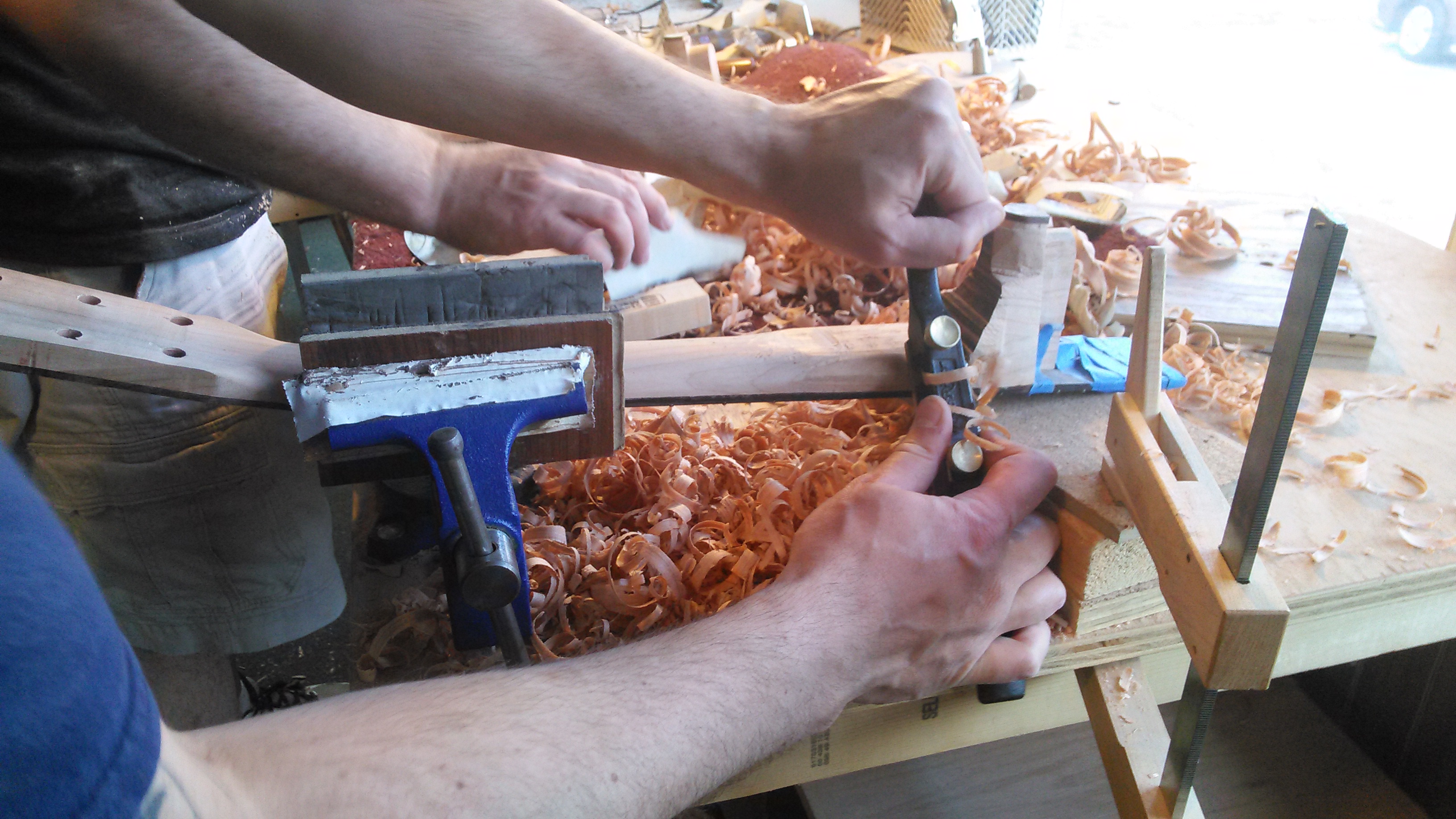
Jim shifts his focus to the neckshaft. He puts his neck up in a vise with the fretboard face down. He sets up a spokeshave for a coarse cut and starts removing material first from the edges. The objective is to reduce the thickness of the neckshaft to the level of the 2 “troughs” that Jim dug out with the rasp. At the same time Jim will be contouring the neck profile, stopping frequently to check his progress. A straightedge will tell you if you are digging too deep in the middle, a common problem when carving with a spokeshave.


80 grit sandpaper held taut against the neckshaft cleans up the coarse marks from the spokeshave and levels the high spots. Chalking or marking the neck with pencil prior to sanding will help you spot high spots and monitor progress.

Chris has roughly contoured the neckshaft and his attention is now turned to blending the transitional area between the headstock and neckshaft.


Chris begins blending the transitional area between the heel and the neckshaft. He uses a combination of spokeshave, rasp, files, sandpaper and scrapers


The neck is complete after a long day of carving! Chris places his neck into the mortise of the body to admire his work. He checks the neck fit. The bridge is taped in place so that the alignment of the neck can be set to the location of the bridge.

Jim’s neck needs some adjustment to bring it into alignment with the center line of the body and the bridge. A small amount of material is removed from the shoulder of the tenon on one side


The neck can now be bolted and the fretboard tongue glued onto the soundboard. There is no glue in the mortise and tenon joint. The bolt on neck is intended for easy removal in the case of future neck repair. Should you have to remove the neck, all you need to do is heat the fretboard tongue to soften the glue and remove the two neck-joint bolts.

The bridge is the most critical glue job of the entire build. The bridge bottom is first radiused to match the radius of the soundboard. This is done simply by sticking sandpaper to the soundboard surface and sanding the bridge to match. The location of the bridge is double-checked to make sure that the location where the saddle slot will be routed is precisely where the scale length ends (distance from the leading edge of the nut to the 12th fret times 2 plus a small amount for compensation). There is a little wiggle room for error because they have not routed the saddle slot yet. The saddle slot will be routed after the bridge is glued to the body.
The bridge pin holes are drilled and bolts are used to locate the bridge and keep it from swimming off its mark when it is glued. The bolts provide a small amount of clamp force, but Chris adds 3 cam clamps for necessary pressure. The bridge should be clamped overnight.

The 2 clamps on the wings of the bridge are not ideal because they are putting pressure on the back plate and top. If Chris pulls the cam too far on those clamps he can easily crack the top and back plate! A better way to clamp the wings is through the soundhole with 2 “Ibex” bridge clamps. It should look like this:
![IMG_20151020_085720[1]](https://ericschaeferguitars.com/wp-content/uploads/2015/10/IMG_20151020_0857201.jpg)
Chris thicknesses the headplate so that the tuning key posts sit at an appropriate height.

Chris and Jim sand a piece of hard bone to fit into the nut slot.


As mentioned previously, the saddle slot is routed after the bridge is glued. This is to ensure optimal intonation. The jig is the StewMac saddle routing jig. The saddle slot is slanted as it is on all steel string guitars to compensate for the difference in thickness of the bass strings in comparison to the treble.

Jim uses a 3 degree reamer to fit the bridge pins. The objective is to get all of the bridge pins to seat snugly and at equal heights to each other.

Chris begins filing string ramps into each bridge pin hole. Each string must be test fit into the pin hole to determine if the ball end of the string seats against the bridge plate. A small LED light and an automotive inspection mirror are used to inspect the inside of the guitar. If the ball end sits up off the bridge plate, then the string ramp needs to be filed deeper to allow more room for the string.

The saddle is rough shaped to fit into the saddle slot snugly. The radius of the fretboard (14″) is sanded onto the saddle top on the belt sander. The saddle is then gently rounded over with a piece 120 grit sandpaper so that the peak of the saddle is directly down the center of its width. The best way to do this is to mark up the top of the saddle with pencil and sand each edge until just a thin ~1/64″ line runs down the middle of the saddle’s width.
With the nut and saddle in place, Chris installs the high and low E strings. He sets the overall string spacing by holding the E strings at a distance from the fretboard edge that looks appropriate to his eye. He then marks the outsides of the strings.

Jim has set his overall string spacing and filed small starter notches to hold the E strings in place. He then used the StewMac string spacing ruler to determine the location of the other 4 strings. The marks are not spaced out equidistant from each other. The marks are further apart on the bass side to compensate for the thickness of the strings.

The next step is to determine the height of the fret tops. Holding a straightedge across 2 frets, fit thin feeler gauges between the fretboard and the straightedge until the straightedge rests right on top of the feeler gauges. Add 0.006″ – 0.008″ to the stack of feeler gauges for either low or high action. Now this stack of feeler gauges can serve as a depth stop when slotting the nut.

Jim demonstrates the proper angle to use when slotting the nut. The idea is that you want each slot to ramp up to the leading edge of the nut. This way the strings vibrating length will begin precisely where the intended start of the scale length is.

Once the nut is slotted the guitar can be tuned up to pitch slowly. Jim and Chris have a completed instrument at this point! They spend an hour or so making adjustments to the truss rod, the nut and saddle to optimize its playability. Hard edges of the body are rounded over and the fretboard is cleaned up and oiled.


Was this useful? I would love to hear your questions or comments! I try to answer every e-mail I receive, so please be patient with me ![]() eric@ericschaeferguitars.com
eric@ericschaeferguitars.com
Want more of this? Subscribe below for Weekly Guitar Making Tips on “The Small Shop Luthier Blog”
Want to learn more? Take a class with Eric Schaefer and build your own guitar in 8 days
